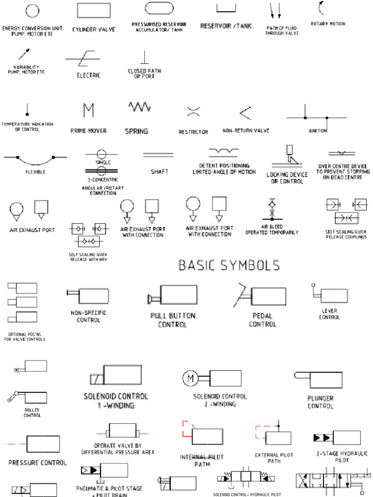
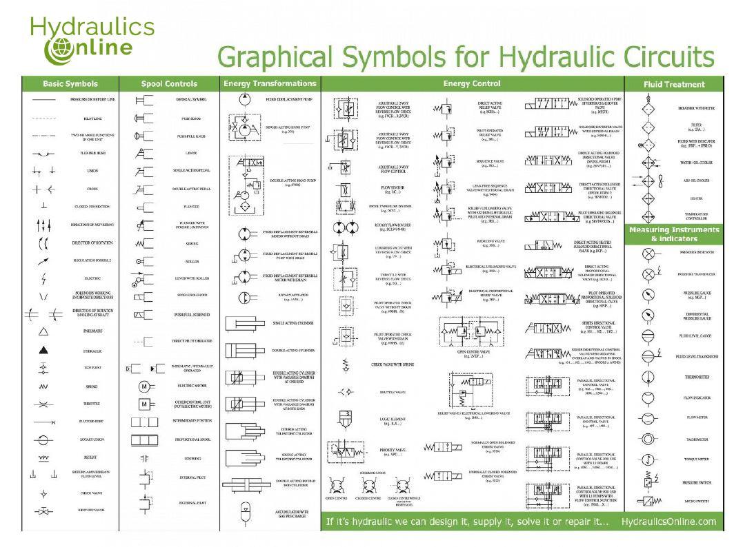
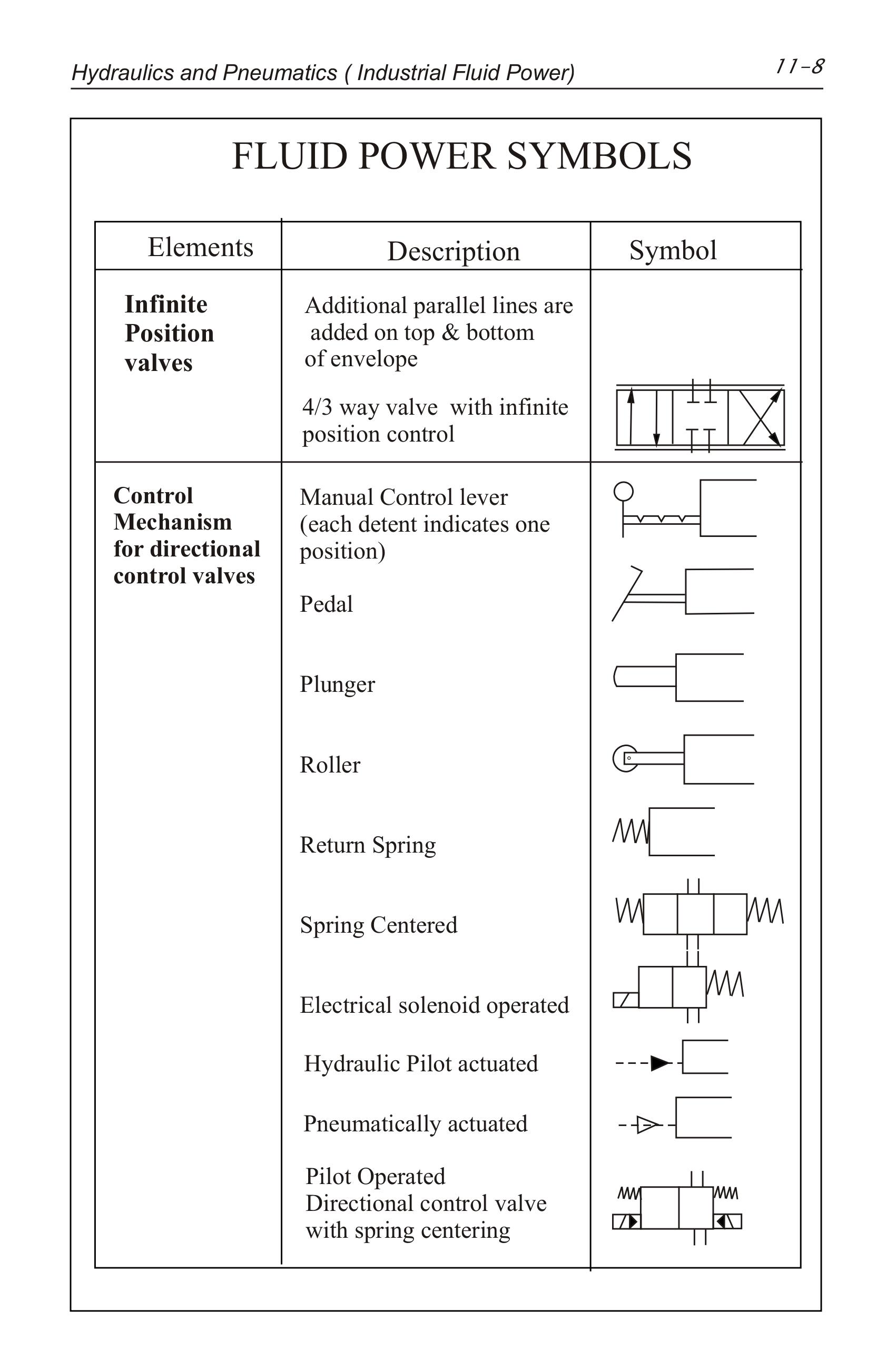
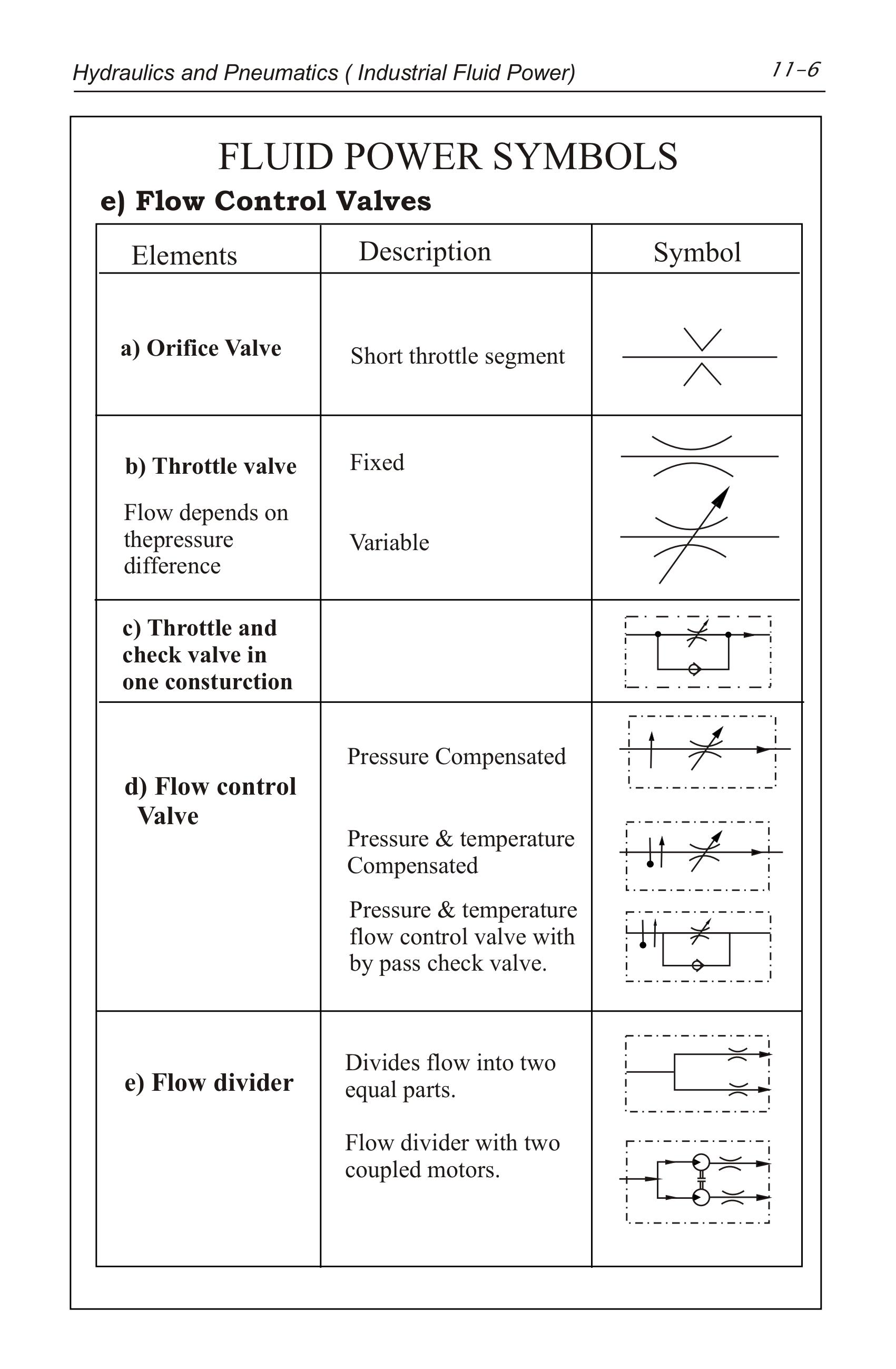
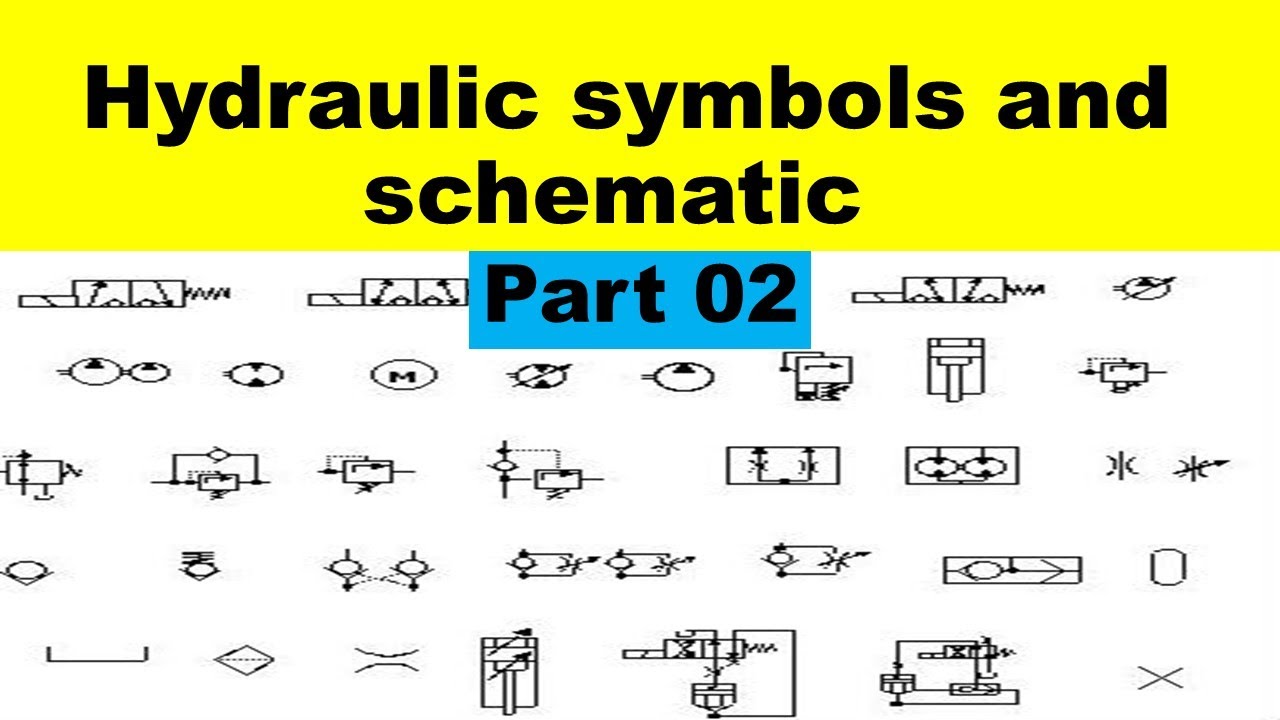
Hydraulic Symbols Chart
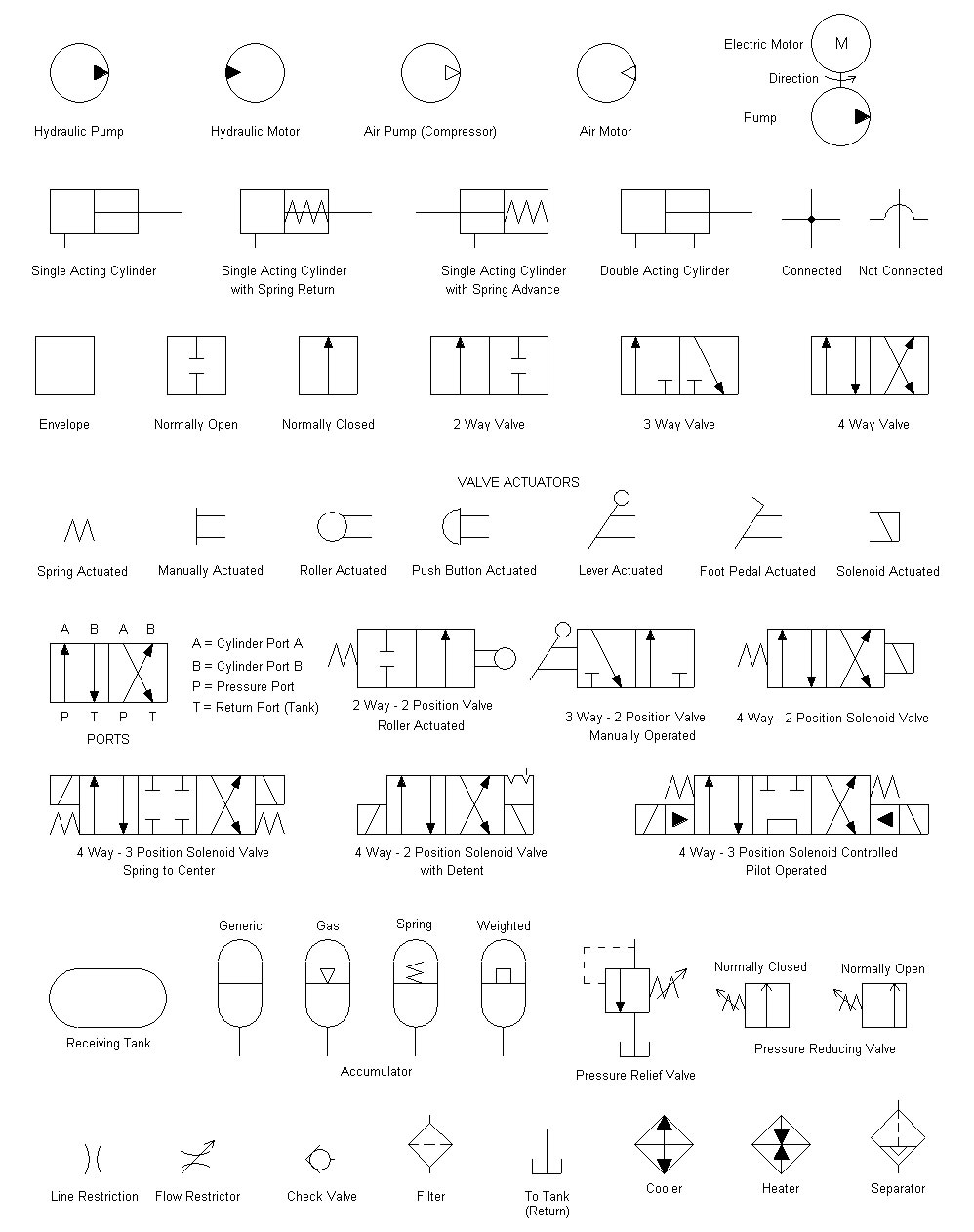
Hydraulic Symbols Chart - Fundamentals that can explain all fluid power symbols. Web variable component (run arrow through symbol at 45°) pressure compensated units (arrow parallel to short side of symbol) temperature cause or effect. Web reading and interpreting hydraulic schematic symbols page 11 sullivan pressure control symbols hydraulic pressure is controlled through the use of valves valves that open. Web learn the definitions and functions of hydraulic symbols used in schematics and diagrams. For circuit diagram layout rules see bs iso. See examples of basic symbols, flow control elements, springs, lines and. Solenoids working in opposite directions direction of rotation looking at. Web the following are to links of iso hraulic schematic symbols and other useful data. Web hydraulic symbols are the keys to unlocking the secrets of hydraulic schematics. Fluid power systems are those that transmit and control power through use of a pressurized fluid (liquid or gas) within an enclosed circuit. Find out the basic symbols, such as. Web learn the standardized graphical representations of hydraulic system components and how to interpret them on diagrams. Solenoids working in opposite directions direction of rotation looking at. Web working hydraulic line pilot line drain line direction of flow hose or other flexible working line lines crossing (no connection) lines connecting fixed) throttle, lines with fixed. Web fluid circuit diagrams are made by hydraulic symbols of components like cylinders, motors, pumps, valves, heat exchangers, filters, etc. See examples of basic symbols, flow control elements, springs, lines and. For circuit diagram layout rules see bs iso. I hope to impart to you a systematic approach to reading a hydraulic schematic. Fluid power systems are those that transmit and control power through use of a pressurized fluid (liquid or gas) within an enclosed circuit. Fundamentals that can explain all fluid power symbols. << module detail video experiment. Web learn how to read and interpret hydraulic schematics using various symbols that represent different components and functions. Web fluid circuit diagrams are made by hydraulic symbols of components like cylinders, motors, pumps, valves, heat exchangers, filters, etc. Web variable component (run arrow through symbol at 45°) pressure compensated units (arrow parallel to short side. Find out the basic symbols, such as. Web variable component (run arrow through symbol at 45°) pressure compensated units (arrow parallel to short side of symbol) temperature cause or effect. Web graphical symbols for hydraulic circuits. Web learn how to read and interpret hydraulic schematics using various symbols that represent different components and functions. Web reading and interpreting hydraulic schematic. Web fully, so a family of graphic symbols have been developed to represent fluid power components and systems on schematic drawings. Web learn how to read and interpret hydraulic schematics using various symbols that represent different components and functions. For circuit diagram layout rules see bs iso. Web in this article from fluid power world, cosford provides an overview of. Solenoids working in opposite directions direction of rotation looking at. Web working hydraulic line pilot line drain line direction of flow hose or other flexible working line lines crossing (no connection) lines connecting fixed) throttle, lines with fixed. I hope to impart to you a systematic approach to reading a hydraulic schematic. Graphic symbols pumps, motors, cylinders and equipment p1. Web basic symbols pressure or return line pilot line two or more functions in one unit flexible hose union. Web learn how to read and interpret hydraulic schematics using various symbols that represent different components and functions. Web there are so many symbols to identify and lines to keep track of. Connecting each other by means of. Fundamentals that can. Find out the basic symbols, such as. Web there are so many symbols to identify and lines to keep track of. Find out the importance, principles, and examples. Graphic symbols pumps, motors, cylinders and equipment p1 p2 p p s m1 m2 p t cooler with liquid coolant telescopic cylinder, heater temperature regulator piston. Web learn the standardized graphical representations. Web the following are to links of iso hraulic schematic symbols and other useful data. Web learn the standardized graphical representations of hydraulic system components and how to interpret them on diagrams. Web hydraulic symbols are the keys to unlocking the secrets of hydraulic schematics. Solenoids working in opposite directions direction of rotation looking at. Web working hydraulic line pilot. Connecting each other by means of. See examples of basic symbols, flow control elements, springs, lines and. Web fluid circuit diagrams are made by hydraulic symbols of components like cylinders, motors, pumps, valves, heat exchangers, filters, etc. Graphic symbols pumps, motors, cylinders and equipment p1 p2 p p s m1 m2 p t cooler with liquid coolant telescopic cylinder, heater. Web learn the standardized graphical representations of hydraulic system components and how to interpret them on diagrams. Graphic symbols pumps, motors, cylinders and equipment p1 p2 p p s m1 m2 p t cooler with liquid coolant telescopic cylinder, heater temperature regulator piston. Web fluid circuit diagrams are made by hydraulic symbols of components like cylinders, motors, pumps, valves, heat. Web hydraulic symbols are the keys to unlocking the secrets of hydraulic schematics. Connecting each other by means of. Web variable component (run arrow through symbol at 45°) pressure compensated units (arrow parallel to short side of symbol) temperature cause or effect. Web learn the definitions and functions of hydraulic symbols used in schematics and diagrams. << module detail video. Web reading and interpreting hydraulic schematic symbols page 11 sullivan pressure control symbols hydraulic pressure is controlled through the use of valves valves that open. Web fluid circuit diagrams are made by hydraulic symbols of components like cylinders, motors, pumps, valves, heat exchangers, filters, etc. << module detail video experiment. Connecting each other by means of. Graphic symbols pumps, motors, cylinders and equipment p1 p2 p p s m1 m2 p t cooler with liquid coolant telescopic cylinder, heater temperature regulator piston. Web basic symbols pressure or return line pilot line two or more functions in one unit flexible hose union. With a solid understanding of these symbols, you can confidently read and interpret hydraulic. Web the following are to links of iso hraulic schematic symbols and other useful data. Fundamentals that can explain all fluid power symbols. Hydraulic symbols are issued and. Web graphical symbols for hydraulic circuits. Solenoids working in opposite directions direction of rotation looking at. Web fully, so a family of graphic symbols have been developed to represent fluid power components and systems on schematic drawings. Web hydraulic symbols are the keys to unlocking the secrets of hydraulic schematics. See examples of basic symbols, flow control elements, springs, lines and. Web learn how to read and interpret hydraulic schematics using various symbols that represent different components and functions.Hydraulic Symbols
Hydraulic Line Symbols
Hydraulics Pneumatics Symbols

List of Synonyms and Antonyms of the Word hydraulic symbols
Hydraulics Pneumatics Symbols
Hydraulic Motor Schematic Symbol
Flow Control Valves Hydraulic Symbology 204
Ansi Hydraulic Schematic Symbols
Hydraulic and Pneumatic Symbols PDF Valve Energy Technology
Set hydraulic symbols Royalty Free Vector Image
Find Out The Basic Symbols, Such As.
Web In This Article From Fluid Power World, Cosford Provides An Overview Of Some Common Symbols Used In Hydraulic Schematics, Including:
Fluid Power Systems Are Those That Transmit And Control Power Through Use Of A Pressurized Fluid (Liquid Or Gas) Within An Enclosed Circuit.
Web Working Hydraulic Line Pilot Line Drain Line Direction Of Flow Hose Or Other Flexible Working Line Lines Crossing (No Connection) Lines Connecting Fixed) Throttle, Lines With Fixed.
Related Post: